SofTutor for MicroStation 3D will teach you how to use all of the icons used in the creation and manipulation of 3D elements. With over 4 hours of instruction, SofTutor will make you a MicroStation 3D power user in hours not months. There are over 250 topics are indexed for quick reference too!
1. Basic 3D Concepts
1.1 MicroStation Basics
1.2 Menus
1.3 Creating a 3D Design File
1.4 The Design Cube
1.5 Converting a 2D File to 3D File
1.6 Controlling The X,Y,Z Axis
1.7 Defining Working Units
1.8 Element Attributes
1.9 Main Tool Palette
2 3D View Control
2.1 Show Display Depth
2.2 Set Display Depth
2.3 Show Active Depth
2.4 Set Active Depth Graphically
2.5 Change View Rotation
2.6 Camera Set-up
2.7 Shade Commands
2.8 Dynamic 3D Viewing (MDL)
2.9 Overview (MDL)
3 3D Coordinates & Tentative Points
3.1 Coordinates in 2D and 3D Design Files
3.1.1 Coordinates DL Keyin
3.1.2 Coordinates DX Keyin
3.1.3 Coordinates XY Keyin Part 1
3.1.4 Coordinates XY Keyin Part 2
3.2 Tentative Point Mode
3.2.1 Tentative Point Command
3.2.2 TP Mode, Distance
3.2.3 TP Mode, Delta
3.3 Setting Locks
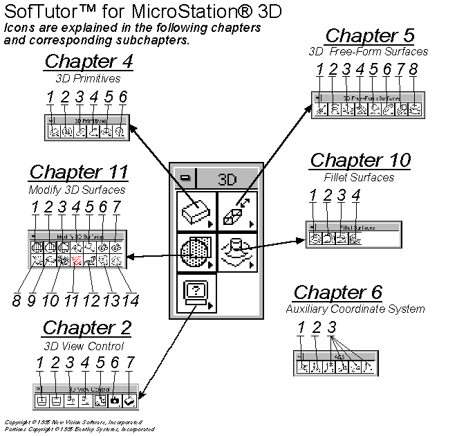
4 3D Primitives (Elements)
4.1 Place Slab
4.2 Place Sphere
4.3 Place Cylinder
4.4 Place Cone
4.5 Place Torus
4.6 Place Wedge
5 3D Free-Form Surfaces
5.1 Construct Surface or Solid of Projection
5.2 Construct Surface or Solid of Revolution
5.3 Place Free Form Surface
5.4 Construct Surface by Section or Network
5.5 Construct Surface by Edge
5.6 Construct Tubular Surface
5.7 Construct Skin Surface
5.8 Construct Offset Surface
6 Auxiliary Coordinate System
6.1 Define ACS (Aligned w Element)
6.2 Define ACS (By Points)
6.3 Define ACS (Aligned with View)
6.4 Coordinate Values
6.5 Settings -> Auxiliary Coordinates
7 Rendering Images
7.1 Rendering Commands
7.2 Global Lighting
7.3 Light Color
7.4 Source Lighting
7.5 Assign Materials to Objects
7.6 Define Materials
7.7 Render Tool
8 Additional Tools
8.1 Capture Image
8.2 Display Image
8.3 Function Key Menu
9 Detail Sheet Commands
9.1 Drawing Composition
9.2 Create a Cross Section
10 Fillet Surfaces
10.1 Construct Fillet Between Surfaces
10.2 Creating Chamfers
10.3 Blending Surfaces
10.4 Blend Surfaces Between Rail Curves
11 Modify 3D Surfaces
11.1 Union Between Surfaces
11.2 Intersection Between Surface
11.3 Differences Between Surfaces
11.4 Trim Surfaces
11.5 Extend Surface
11.6 Split Surface
11.7 Stitch Surface
11.8 Change Surface Settings
11.9 Change Surface Normal
11.10 Change Surface Boundary
11.11 Delete Surface Boundary
11.12 Change Active Solid or Surface Status
11.13 Punch Surface Region
11.14 Extrude Surface Region
12 MDL Commands
12.1 MDL Magnifier
12.2 MDL Level Use
12.3 MDL View Control
13 Labs
13.1 Lab 1: Two-Dimensional Profiles
13.2 Lab 2: View Control Commands
13.3 Lab3: Change Surface Normal
13.4 Lab 4: Construct a Mechanical Part
13.5 Lab 5: Creating a Desk
13.5.1 Changing Background Color
13.5.2 Setting Working Units
13.5.3 3D Palettes
13.5.4 Creating a Table Top
13.5.5 Creating a Desk Leg
13.5.6 Defining 3D Space
13.5.7 Create a Drawer
13.5.8 Mirroring Elements to Create a Desk
13.6 Lab 6: Creating an Office
13.6.1 Convert 2D File Into 3D File
13.6.2 Convert 2D Element into 3D Element
13.6.3 Grouping Elements with Flood Command
13.6.4 Select Elements Using Maximum Gap
13.6.5 Create a Window
13.6.6 Global Lighting
13.6.7 Assign Materials
13.6.8 Fly Through
 |
||||||||
 |
||||||||
| Return to MicroStation Products Page | Return to NVSI Home Page | |||||||
| New Vision Software does not grant permission to any party to redistribute any material without the written consent of New Vision Software, Incorporated. Copyright © 1995-2002 New Vision Software, Incorporated All Rights Reserved. | ||||||||